The ZS6BKW Antenna
6 bands (40 / 20 / 17 / 12 / 10 / 6m.) without a tuner or traps!
When OM Louis Varney, G5RV designed his famous antenna in the 1950's, it performed excellently with the equipment of that day and age. With today's radio's, on the other hand, things are different. This led OM Brian Austin, ex ZS6BKW (now GØGSF) to redesign the G5RV, using modern antenna modeling software - something that was was not available when the G5RV was designed. He found that shortening the two legs of the G5RV dipole and lengthening the matching stub (the balanced feed line) resulted in an antenna that provides a good match to the 50 ohms impedance of today's transistorized radio's. This allows the antenna to be used on five bands without an antenna tuner! And as an added bonus, it was later discovered that the ZS6BKW antenna covers not five but six bands, as it does 6m, too, something that the original G5RV did not cover at all!
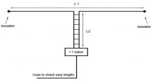 However, there is some bad news, too. On 80m and 15m the ZS6BKW design performs less well than the original G5RV, while on 30m it is just as bad. Also, the antenna's performance appears to be rather dependent on how well it is installed. If it is not high enough above ground or does not keep sufficiently clear of trees, buildings or conductive objects, performance can be affected rather seriously. However, in this respect it does not differ markedly from the original G5RV, which behaves similarly.
G5RV design, the dipole length (L1) was 31.1m while the matching section (L2) was 10,37m of open line. In the optimized design by ZS6BKW the dipole itself is slightly shortened to a length (L1) of 28.4m, while the matching section (L2) is longer, and depends on the velocity factor of the feed line used. Different versions of this design circulate on the Internet, typically using 300 ohm tape (the type with a velocity factor of 0.85, and L2 being 11.1m) or using 450 ohm window line (with L2 being 12.2m). However, the best, cheapest and easiest way to make the matching section is to use ladder line, which can be easily constructed using Instant Ladder Line clip-on wire spreaders. In this case L2 is 13.08m.
While various literature claims that a 1:1 (or almost 1:1 match) without a tuner on various frequencies can be achieved, this seems more due to the lossy coax used by the ham doing the measurements than the antenna's performance! (Note that because lossy coax also dampens the reflected wave, coax loss will result in a better SWR measurement at the transmitter!) In OM Brian's own 1985 publication he merely speaks of "an acceptable match", better than 2:1 on five bands, which seems much more realistic. And that is fine - better than 2:1 is more than sufficient. A 1:1 match is not required, contrary to what many hams these days believe!
The table below lists a few SWR figures that compare theoretical (calculated) values found in literature, to the measured values of the author's own ZS6BKW antenna, as well as to the G5RV. (Only theoretical values for the latter, but past measurements done on actual G5RV's show that these match the actual performance fairly well.)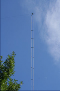
- Band 80 40 30 20 17 15 12 10 6
- ZS6BKW, literature 8.3 1.1 87 1.2 1.4 80 1.2 1.5 1.5
- ZS6BKW, measured >10 1.7 >10 2 1.4 >10 2 2 1.7
- G5RV 3.2 4.8 >10 2.5 >10 6.8 3.6 >10 N/A
(Note: these are the "best" SWR figures; they will of course vary while tuning across the band. The fact that the measured SWR values are higher than the ones in literature is probably due to "end effects".)
(Updated, 1 Jan. 2011) After having read this article, Brian Austin has responded to point out that his antenna design has been optimized for feed lines with an impedance of around 400 ohms. With this feedline impedance a better SWR will be obtained than when using a ladder line with an impedance in the 600 ohms range. So strictly speaking, a ZS6BKW antenna with a ladder line instead of window line is not a "real" ZS6BKW antenna.
While OM Brian is of course entirely correct in saying this, the fact remains that the above performance figures are still very usable on most frequencies, and an antenna built with ladder line that is on hand performs much better than one that requires window line that isn't! (End of update.)
Balun or no balun?
A lot of "religious debate" on whether or not to use a balun between the coax and the matching section has taken place over the years. Most of it is based upon OM Varney's own remarks on the subject, and experiments by other hams. However, Varney's statement that he did not notice any difference with or without a balun, and the conclusion that one is therefore better off without one, date from the 1960's and apply to the equipment of that era. Many hams, meanwhile, have experimented with 4:1 voltage baluns, which introduce a mismatch because the feed point impedance of the matching stub is much close to 50 ohms than to 200 ohms.
The fact of the matter is that any way you look at it, it is never a good idea to attach an unbalanced coaxial cable directly to a balanced load (which this antenna is). It introduces unbalanced currents in a balanced system, thus causing it to perform wildly different from what theory predicts, not to mention the fact that it causes shield currents in the coax, resulting in RF in the shack and TVI. A proper 1:1 current balun (i.e. a choke) between the coax and the balanced antenna feed point is therefore to be recommended.
Instant Ladder Line
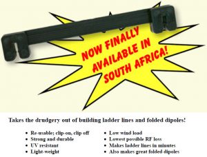
Clip-on Wire Spreaders
Why Ladder Line?
 When faced with the need to feed an antenna, most people automatically reach for coax. Coax is convenient and easy to install, it is shielded so you don't have to worry about RF, and everyone uses it so it must be much better than balanced open line, right?
So let's have a look at how coaxial cable (say, RG-213) compares to typical 600 ohms ladder line.
- RG-213: Shop-bought at considerable expense; radiates RF when mismatched, typical loss: 4.8dB / 100m @ 30MHz.
- Ladder line: Easily constructed for a few cents per meter; radiates very little RF even when severely mismatched; typical loss: 0.33dB / 100m @ 30MHz.
Any questions?
RF Radiation
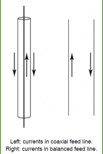
First of all, it is a common misconception that because coaxial cable is shielded, it will not radiate RF. True, the shielding does prevent RF from being radiated by the cable, but only if there are no shield currents, which occurs whenever current flows in an unbalanced manner along a transmission line. With coaxial cable this means that current exists on the outer surface of the braid and since there is no equal and opposite current in close proximity to counterbalance its effects, the coax will radiate. That such a current exists is purely and simply a matter of balance; it has nothing whatsoever to do with the degree of mismatch that may exist between the impedance of the load and the characteristic impedance of the coax. Standing waves, so caused, thus make no difference to whether the coax radiates or not. The only factor that causes outer-braid current to occur is the degree of unbalance that exists between the line and the load. It is for this reason that a balun is used to correct for any such unbalance. (With thanks to Prof. Brian Austin for correcting our previous statement and Dr G.W. Immelman for his assistance).
And of course no antenna is 100% ideal in the real world. The balun (if there is one at all!) may be imperfect. The frequency at which the antenna is being used is unlikely to be the exact single frequency at which it resonates. There may be an unbalance in the dipole's feeding arrangement. The shield of the coaxial cable may pick up a part of the RF that is being radiated by the antenna. These and many other real-world factors practically ensure that in practice a coaxial cable will generally radiate RF, both in and out of the shack. Which is of course why so many radio hams resort to ferrite and chokes in an attempt to suppress shield currents and the TVI they cause!
A balanced feed line, on the other hand, relies on two parallel conductors positioned very close to each other, i.e the distance between the conductors is minute in comparison to the wavelength of the signal. This means that the radiation from both conductors almost cancel each other out. Almost, but not quite, because 100% cancellation would require the conductors to be so close to each other that they literally occupy the same space, which is of course impossible. In practice, though, the distance between the conductors is still easily small enough so that radiation is negligible. Note that this is not dependent in any way on match or mismatch: as long as the system remains balanced, radiation will be extremely low (usually much lower than that of coax) even when the feed line is severely mismatched.
This is perhaps the most important difference between a balanced feed line and coaxial cable: the amount of radiation from the cable is constant, and not dependent upon length, frequency or resonance. With coaxial cable, a bad SWR will immediately result in RF in the shack, as well as TVI. With a balanced feed line, on the other hand, even the worst mismatch will not increase the amount of RF it radiates. Due to its intrinsic low loss characteristics a balanced feed line will also allow for a very high SWR without significant power losses. This means that this type of feed line can be used to feed the proverbial random length dipole on any frequency (with a trans-match between the feed line and the radio) without any serious consequence. Case in point: before coaxial cables came along, few radio amateurs had ever used an SWR meter, and the antenna systems they used in those days often presented "bad" SWR's of 8:1 or 10:1 or worse. But because balanced feed lines were used, this was never a problem. All that mattered was to tune up the plate and load capacitors on the transmitter to match impedance's, so that RF power would be transferred correctly to the antenna system, and off you went. Only when coax became popular, the SWR meter became the most often used instrument in the shack, and radio hams started to spend a lot of time hunting for that elusive 1:1 SWR.
Cable Types
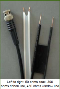 Balanced feed line cable comes in various forms, shapes and sizes. One of the oldest commercially available types is the well-known 300 ohms ribbon cable (also known as tape or twin lead) which was used for FM radio and VHF television antennas before 75 ohms coaxial cable became the standard for that application. Ribbon cable comes in two varieties: one for indoor use and one for outdoor use. The latter is black, and can be either a thin ribbon with a dumbell-shaped cross section, or a thick ribbon with a cylindrical or lenticular cross section. Solid and foamed dielectrics may be used. This type of cable is difficult to obtain in South Africa, and often expensive when found.
The other variety is known as window line. Unlike ribbon cable it is not a continuous ribbon, but it has rectangular "windows" cut out of the centre. This reduces weight and loss, and increases the velocity factor of the cable (see below). The characteristic impedance is generally 450 ohms, although 460 and 480 ohms types are also manufactured. Unfortunately this type of cable is almost impossible to obtain in South Africa. Generally it has to be sourced from overseas at considerable expense, and it is not cheap to begin with.
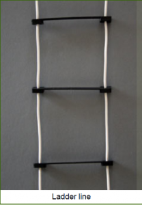
The third form, ladder line, is not readily available commercially, but ideally suited for "home brewing" by the radio ham. It uses regular wire which may or may not be insulated, it is inexpensive, and it can take a considerable amount of RF power. The characteristic impedance depends on wire thickness and spacing, but is generally in the order of 600 ohms.
Comparison
The following table compares some typical characteristics for various cable types.

Legend: Zc is the characteristic impedance in ohms; Vf is the velocity factor; Loss is specified in dB per 100m @ 30MHz. Note: some cable types are available with different types of dialectic (e.g. solid vs. foam) which improves their loss figures and changes their velocity factors.
Keep in mind that the typical loss figures for feed lines (like the ones in the table above) assume that the feed line is correctly terminated. If there is a mismatch (e.g. when using a short, non-resonant antenna) the signal bounces back and forth across the feed line, and losses increase exponentially. If coax is used in this case, only a small fraction of the RF energy actually reaches the antenna, while the rest disappears in coaxial losses! The dramatically lower loss of ladder line really comes into its own here. For more details see the article on random length dipoles.
Installation tips
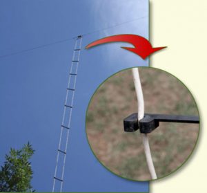
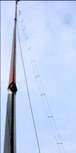
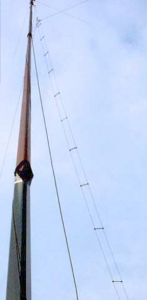
While coaxial cable can be mounted against walls, steel towers, gutters etc., ladder line should "hang freely". This can be easily achieved by suspending the antenna from a pulley or stand-off at the top to keep it from touching the mast; the bottom end of the ladder line can be easily suspended from any convenient support with nothing more complicated than a piece string or rope.
In South Africa a popular way of getting coax into the shack is to run it through the hole blocks found in most walls. The same method can be used for ladder line. In this case both conductors are fed through the hole block using different holes with appropriate spacing. Note: if there is a metal screen between the inner and outer hole block, openings in its mesh should be made to prevent the ladder line conductors from touching the screen.
With coax it is easy to run a cable through an open window and then close the window, clamping the cable between the window and the frame. Ladder line, on the other hand, should be kept a short distance away from metal, because the RF field of both wires may couple with metal and therefore unbalance the currents in both wires, causing the ladder line to radiate. In practice this is not a problem: a few simple stand-offs are enough to keep the feed line 8-10cm away from metal. This is pretty much the only drawback of ladder line: you can't tape it to your metal tower or roof gutters like you can do with coax. It is also not advisable to clamp ladder line between a closed window and the window frame, unless the window frame is entirely made out of wood and there is no proximity with any metal parts. Given the fact that most window frames in South Africa are made out of steel, running a balanced feed line through the window and then closing the window to clamp the cable in place is usually not recommended.
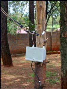
If it is impossible or impractical to use ladder line all the way into the shack, the last few meters may be covered using coax. This is not preferable, but sometimes it's the only practical choice. In this case a balun should be used between the coaxial cable and the ladder line to prevent excessive shield currents in (and therefore excessive RF radiation by) the coax. Baluns may be housed in a standard electric box which can be mounted on a pole, tree or wall. Ceramic or plastic insulators, cable ties and/or rope can easily be used in a variety of ways to suspend the ladder line and keep it hanging freely.
The impedance of ladder line is a factor of the diameter of the wires used, and the distance between the wires. Keep in mind, though, that one of the most important properties of balanced feed lines is that the characteristic impedance is not critical! Anything within reason (200 ohms, 300 ohms, 450 ohms, 600 ohms, etc.) will do nicely.
See the baluns page for more tips on baluns.
Specifications
Nominal physical product characteristics
- Material: polypropylene with UV blocker
- Weight: 2.5 grams
- Outer dimensions: 98.5 x 14.5 x 5.5mm
- Wire spacing (conductor centre to conductor centre): 84mm.
- Usable wire diameter, insulated, including insulation: ± 2 - 3.5 mm.
- Usable wire diameter, bare: ± 2 - 2.5 mm.
- Recommended spacing between spreaders: ± 50cm.

Feed line impedance's for various wire diameters
The following table on the left shows the nominal characteristic impedance (Zc) of a ladder line constructed with Instant Ladder Line clip-on wire spreaders, for various wire diameters. Note: this is the diameter (i.e. not the cross sectional area) of the conductor and does not take into account the thickness of the insulation. The conversion table on the right may help you to determine the wire diameter from AWG (American Wire Gauge) and cross sectional area wire thicknesses specifications.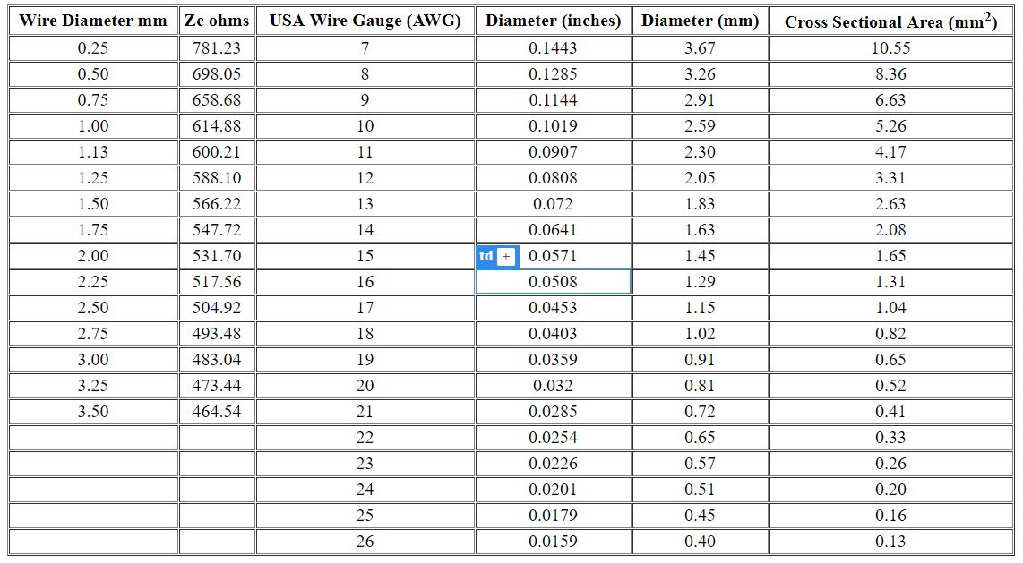
This loop was built to get some DX from the SE and NW. Some mods were done to an antenna devised by L. Cebik, W4RNL. My attempt was to get a "Quiet Antenna," with a low take-off angle, a 50-100 OHM impedance and something structurally sound.
Most of you know that a square loop is 90-100 OHM impedance, the largest capture area gives you the most gain. Ex: Circle best, Square next, Rectangle lower, Triangle worst. Each has a bearing on your impedance.
I chose the 24" x 12" VOVPL. The term VOVPL - stands for Vertical Oriented Vertical Polarized Loop. I stay away from the Horizontal Oriented as hams call them "Cloud Burner", good for melting snow and for keeping earthworms warm. This comment can start a good discussion.
The corner Feed provided about 75 Ohms impedance. The centre of the vertical side about 50 Ohms and the centre of the bottom (horiz) side about 100 OHMS. Note X on Diagram.
Corner feed was chosen because I could tie the 75 OHM coax to the guy rope. I did not like the centre vert or the centre horiz as it is unstable. Besides the corned feed gives you a vertical and horizontal polarization.
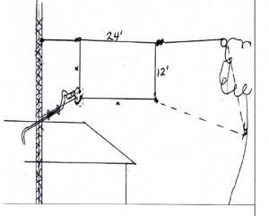
Most formula's call for Circ' = 1005/ Freq (Mhz). I have had good results with 1023. Also it is easier to cut than to add wire. See the diagram on above. Corner feed with 75 OHM coax is good because you can tape or Ty-wrap it to the rope and tower. But there is always a BUT. It is only a one band antenna (20m). A multiband antenna was wanted - so twin-lead was used (not 300 OHM).
You know the black twin lead that Sask-tel uses for telephone service to your house - it is 90 Ohm twin lead. Now they are installing Fibre Optic line and for a contribution to their coffee fund the service centre will you you some. But - another BUT, you have to stand if off from anything metal (tower, eaves troughs, etc). I canvassed my neighbours for broom handles (wood) or broken hockey sticks.
Drilled a hole at the end and Ty-wrapped twin lead - in to it, then Ty-wrapped broomstick to tower. With a tuner it loads easily on 20, 17, 15, 12 and 10. With coax feed SWR was between 1.2 and 1.7. We like the antenna, my YL uses it to talk to the U.S.A girls on the YLRL Tangle Net. Mine is broad site to Florida, Caribbean and South America and in the other direction to Alaska, Korea and Japan. Signals are good and the noise cancelling effect of a loop helps. At my age I am downsizing, no more beams, just wire loops, who cares if I can't rotate it.
Thanks to Lloyd Cebik for the idea and the man at RARA flea-mart who wanted me to write more articles.
In using coax, use an inverted drip loop to avoid water ingress and centre conductor goes to Vertical part of loop and shield to Horiz part.
73 Harv, VE5AC
A Quick & Easy 20m Folded Dipole
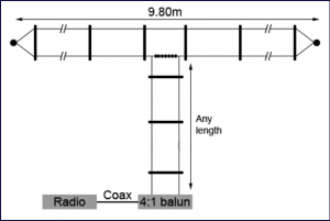 Since the 20m band is still the main "long haul" band and most popular for DX, it makes sense to have an antenna handy for use on this band at all times. Especially when conditions suddenly improve or if a rare DX station is suddenly heard, there is little time to tune up a multiband antenna. The 20m folded dipole antenna presented here performs well, needs no tuning, and can be assembled and installed in no time at all. The advantage of a folded dipole over an open dipole is that a folded dipole is less susceptible to local QRM (it's far less sensitive to the near field) and therefore sounds much "quieter" than a comparable open dipole, which is obviously a valuable property when hunting for weak DX signals!
While the length of the antenna specified here is for the 20m band, its dimensions may of course be multiplied or divided as desired to make the antenna resonant on other bands. Because the feed point impedance of a folded dipole is higher than that of an open dipole, a 4:1 balun is required between the open feed line to the antenna and the radio.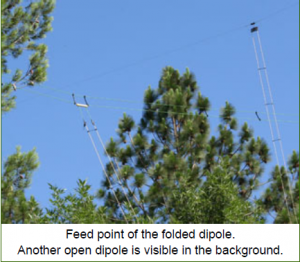
Construction is fairly straightforward. Instant Ladder Line clip-on wire spreaders are used to construct both the dipole itself and the ladder line that feeds it. An insulator (e.g. a plastic "dog bone") between the two points where the ladder line is connected to the dipole takes the strain and keeps the antenna in shape. The coax between the 4:1 balun and the radio should be kept as short as possible, but if absolutely necessary the balun can be mounted outside the shack, with coax going through walls, windows etc.
While an open dipole, when fed with a ladder line, can be used as a multi-band antenna on practically any frequency, the same is not true for the folded dipole. The latter can only be used on odd harmonics of its lowest resonant frequency. E.g. a folded dipole for the 80m band can be used on 30m but not on 40m and 20!
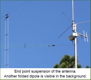 If properly constructed, this antenna will give a 1:1 SWR at the desired center frequency, with no more than 1.4:1 at the band edges. It can be suspended from poles, trees or any other available support. Keep in mind that higher is always better. Even more important is to keep the end points of the antenna well clear of metal parts such as masts and roof gutters, since close proximity between the antenna end points and metal will seriously de-tune the antenna.
The Random Length Open Dipole
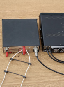
It is a commonly held belief among radio amateurs that an antenna has to be resonant in order to be effective at all. In practice, though, antenna resonance plays only a minor role in the efficiency of an antenna. In fact there are antenna's that are deliberately designed not to resonate on a single frequency, such as the various members of the family of traveling wave antenna's. Whip antenna's for mobile use are also non-resonant more often than not. Commercial and military antenna's are frequency non-resonant. All these antenna's present a proper load to the transmitter only by virtue of the matching networks built into them, but the radiators themselves are essentially non-resonant. The popular 5/8 wavelength mobile whip antenna is a good example.
To re-iterate (perhaps to the howls of outrage from many radio hams who believe otherwise): there is no need whatsoever for an antenna radiator to have a length that bears a distinct, fixed relationship to the operational wavelength. It is more convenient if it does, because then we won't have to do any impedance matching, and we won't be severely punished for using a lossy coaxial feed line, but it is by no means necessary.
The misconception that an antenna has to be resonant, and that therefore its length must be a function of the operational wavelength, is largely caused by he fact that "no antenna is an island". What matters is not just what goes on in the radiator. More important is what goes on in the antenna system as a whole -- the antenna, various sections of feed line, and any impedance transforming components such as stubs, matching sections and "antenna tuners".
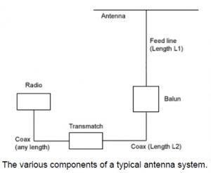 Let's start with that much-hallowed and much-maligned "antenna tuner" - one of the many frequently misunderstood and hotly debated components in the system. Its name is in fact a double misnomer. First, it does not tune the antenna - in order to do that, it would have to change the resonant frequency of the radiator, which is a function of mechanical length, induction, capacity and other fixed physical characteristics. Instead all a "tuner" does is to match the impedance's of whatever is connected to it. It is a variable impedance transformer, no more, no less. Therefore it is more properly known as a "trans-match" which is a much better name. Second, it does not match the antenna to whatever is connected to it. It matches the antenna system (feed lines, stubs, radiators and what not) to the radio. Simply put, the trans-match is to a radio what the gearbox is to a car engine.
So. Having established that we need to look at the entire antenna system rather than just at the antenna itself, the first components we should consider are the ones that make up the feeding arrangement: the feed line and the trans-match (if any). It is here where the resonance or non-resonance of the antenna has the biggest impact. If the feed line is made from coax, then a non-resonant antenna system will not perform well: the relatively high losses in the coax will ruin the antenna system's efficiency, and the shield currents will pour large amounts of RF into the shack where it causes burnt fingers and TVI. To simplify: if there is a mismatch between the radiator's impedance and the feed line impedance, then RF energy will be reflected back and forth across the feed line until it has either been radiated by the antenna, or dissipated by the various loss factors in the system. The loss of the feed line and losses occurring in the trans-match are the most important loss factors here. If the feed line is coax (which has a relatively high loss factor) then the feed line losses will be the dominant ones, even if "low loss" coax is used!
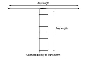 If, on the other hand, the antenna is fed via ladder line, none of this happens. As long as it's balanced, ladder line radiates a negligible amount of RF even when severely mismatched, and its extremely low loss means that the efficiency of the antenna system as a whole is barely affected. This allows us to use an antenna that is as large as is practical (given space restrictions and the like) but the length of which is not necessarily a multiple of a quarter or half wavelength. While the old rule of "the bigger the better" still holds, that largest practical length can be a totally random length with respect to the wave length!
Of course that does not mean that the physical dimensions of an antenna are now totally irrelevant when the antenna is fed through a ladder line. The impedance of the feed line presented to the RF source (radio or trans-match) at a certain frequency is dependent on both the length of the radiator and the length of the ladder line, which in this configuration acts as a matching section. This impedance may be very high (a complex impedance of, say, 2000 + 2000 ohms is very well possible) which means that when power is applied, the voltages on the feed line can be very high. This may lead to arcing and (depending on design) excessive losses in the trans-match. Also, the efficiency of the antenna as a radiator when transmitting, and the amount of EM field it will pick up when receiving, is still a function of its length. An antenna can be non-resonant and work well, but within reason - don't expect to be able to use the proverbial knitting needle on 80 meters and get useable results! Ladder line works well, but is not a miracle "cure-all". The laws of physics still hold, and bigger is still better.
That said, a smaller antenna that fits within what little space you may have, is a lot better than a larger one that doesn't! If all you have room for is an antenna with an oddball length of, for example, 13.8 or 16.2 meters, or any other random number, just use what you have! As long as you don't mind tuning up your trans-match whenever you change frequencies, and the trans-match can handle the weird and wonderful impedance's presented to it by the feed line, it will get you on the air very well. If the trans-match struggles to match the antenna system to your radio on some frequencies, try shortening or lengthening the antenna and/or feed line in small steps. Soon you'll have a length that will be easy to "tune up" on most (or even all) bands.
A random length dipole can also be installed in just about any configuration that size limitations make necessary: as a V, as an inverted V, as an inverted L, or any other letter of the alphabet you care to use. Just make sure that the end points of the dipole stay well clear of the ground and of metal objects (masts, roof gutters, etc.) to prevent "end effects". And keep in mind that the voltages at the feed line terminals may be high on some frequencies!
Avoid using a balun! Connect the ladder line directly to the trans-match. The wild impedance swings that you can expect in a random length dipole and ditto feed line can make a balun very nervous: the mismatch will often cause excessive losses within the balun, especially if it is a type with a ferrite core, and saturation can easily occur. This will cause the balun to overheat from the RF energy that is dissipated in it, and the efficiency of the antenna system as a whole goes of course right out the window if that occurs. Note that most trans-matches are of an unbalanced design, and if they have terminals for balanced feed lines that often means there is a balun built into the trans-match. If you decide to go the route of a random length, ladder-line fed dipole, you might want to consider a balanced trans-match, or a Z-match with an extra coil winding to drive a set of balanced terminals. Many designs are available, such as the one by WB3GCK. Some experimentation may be necessary.
Recommended reading: The Lure of Ladder Line, published in QST, December 1993.
(Note that what is called "ladder-line" in this article is actually window line.)
BALUNS
The antenna terminal on a modern radio is coaxial (usually a PL259 connector) and therefore unbalanced. The radio chassis sits at zero potential (if all is well, that is) and the center pin of the coaxial connector carries the RF signal. A dipole antenna, on the other hand, which is often used for HF operation, is a balanced antenna. Simply connecting an unbalanced system to a balanced system is never a good idea! If coaxial cable is involved, its shield will carry strong RF currents which will be radiated where they will do the least good. This will cause RF in the shack, TVI, etc. The radio's chassis and everything connected to it will be "hot", resulting in blistered fingers due to RF burns. Obviously some conversion from unbalanced to balanced is required in order to connect these two different systems. Enter the balun. As the name (bal-un) implies, a balun matches a balanced system to an unbalanced one. In addition to that, baluns can (but not necessarily do) perform impedance transformation as well. The 4:1 balun, which matches a 50 ohms unbalanced radio to a 200 ohms balanced dipole, is a popular example.Voltage vs. current baluns
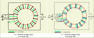
Baluns can employ either one of two principles. On the one hand there are voltage baluns, which are essentially auto-transformers. On the other hand there are current baluns which are based upon the principle of suppressing or neutralizing common-mode currents. And in-depth treatment of the theories behind the various balun systems and how they interact with feed lines is beyond the scope of this article. Instead, let's have a look at the four baluns that are most common in practice, and see how they compare. The 4:1 voltage balun is the most commonly found balun. The voltage balun (also known as the "Ruthroff" balun) is actually a simple transformer. Current from the unbalanced terminal (the center pin of the coax) is fed directly to one of the balanced terminals, and runs through the top half of the transformer windings as well. This induces a similar current in the bottom half of the transformer windings, but because the top of the bottom transformer half is at zero potential, the lower balanced terminal develops a voltage equal but opposite to the upper one.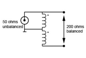 While this design is the most common one, it is by no means the best! The main problem is its flawed symmetry. The impedance of the top half of the transformer is switched in parallel with the (typically 50 ohms) impedance connected to the unbalanced terminal, while the lower half of the transformer is not. Especially at higher frequencies, where the inductance of the transformer windings increases, this means that the voltage developed across the upper transformer half is loaded by the unbalanced input impedance, and therefore drops. This is not true for the lower half of the transformer. As a result the signal across the balanced terminals is far less balanced for higher frequencies. This unbalance will cause a balanced feed line to radiate RF.
The 1:1 voltage balun is a variety on the previous one. Here the current drawn from the unbalanced terminal (the center pin of the coax) is fed not through one but through two transformer windings in series. The upper balanced terminal is connected to the connection point of the two windings. The third (bottom) transformer winding forms an arrangement similar to the one described above. In this configuration the amplitude of the unbalanced signal is equal to that of the balanced signal, since both of them are developed across the same number of transformer windings. In the 4:1 voltage balun the balanced signal was developed across twice the number of windings compared with the unbalanced signal, which means (this being a transformer) that the voltage is doubled while the current is halved, resulting in an impedance transformation factor of 4:1. The 1:1 balun performs neither voltage nor current transformation, hence the impedance transformation factor is 1:1. It does, however, experience the same problems with flawed symmetry and the resulting unbalance at higher frequencies!
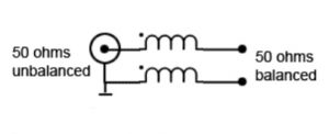
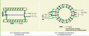
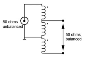 The 1:1 current balun is also known as the Guanella balun or a choke. This is one of the simplest baluns. It is based on suppression of the common mode current in the feed line. The current through the upper winding induces an equal but opposite current in the bottom one, with a voltage developed across the bottom winding equal and opposite to the one across the top. This annulls the voltage on the bottom balanced terminal, thus keeping the chassis of the unbalanced side at zero potential. In practice this balun often takes the form of a coaxial cable wound into a coil. Its main disadvantage is that its efficiency depends entirely on the coil inductance, which should be infinite in order to achieve 100% suppression of feed line common mode currents. In the real world this inductance is finite and frequently low, which limits the efficacy of this balun.
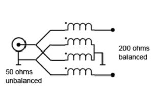
 The 4:1 current balun (Guanella balun) may look a bit confusing, but in fact isn't all that hard to understand. It consists essentially of two 1:1 Guanella (current) baluns, the unbalanced sides of which have been switched in parallel, while the balanced sides are in series. This means that both 1:1 baluns will each develop the same voltage on the right hand side as on the left hand side (they have a transformation factor of 1:1 after all) but because on the balanced side these two voltages are switched in series, the voltage on that side doubles. With twice the voltage (and therefore half the current) at the balanced side, the result is a 4:1 impedance transformation. Both 1:1 baluns which make up the 4:1 variety may be wound on different cores, or on the same core. The main disadvantage of this particular balun is that the characteristic impedance of the windings themselves should be twice that of the unbalanced impedance and half that of the balanced impedance. In other words, in order to get a 1:1 SWR at the 50 ohms side, the characteristic impedance of the windings ideally should be exactly 100 ohms, which is extremely hard to achieve in practice. On the other hand, while the SWR meter may not show a 1:1 match with a dummy load, the symmetry of the signals at the balanced end of this balun will always be 100%, which cannot be said for the other three balun designs shown above!
Balun cores: air, ferrite or powdered iron?
Many balun designs can be found on the Internet. A number of these are "air wound" baluns, consisting of wire or coax wound across a former (e.g. a plastic tube) filled with air. This makes sense in countries where four figure power levels are legal (or at least common) since an air core is, for all practical purposes, impossible to magnetically saturate. In other countries such as South Africa, however, where 100W is the most common maximum power level, and with a happy few owning a "foot warmer" that pumps out 200 or even 400W, it is very well possible to use properly selected powdered iron or ferrite cores without causing these cores to saturate. Since the proper functioning of all baluns discussed here depends on self-induction and magnetic coupling, the higher magnetic permeability of a core is preferable to the low permeability of air. Baluns based on air cores often leave a lot to be desired, with their efficacy being limited by the low induction and loose coupling of the windings, especially on lower frequencies.
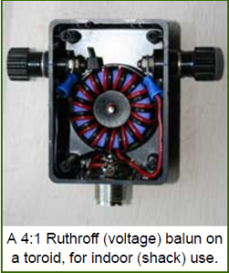
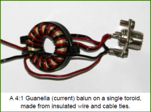 Various options are available for balun cores. The top of the range (and of course the most expensive option) is the ferrite toroid core. These can be obtained in South Africa from suppliers such as Mantech or RS components. They can be hard to find and somewhat pricey, but they are available. Ordering ferrite cores in larger batches may be easier than obtaining single ones, so consider making it a club project! Various ferrite mixes are available. Without going into the details of ferrites (about which many volumes have been written), an excellent all-round ferrite mix for balun cores is 4C65. The amount of power the balun can handle is in no small measure determined by the size of the toroid - the bigger, the better. In practice a 36mm toroid is more than sufficient to handle 100W, provided that the impedance mismatch isn't too great.
(Updated, 1 Jan. 2011) The biggest problem with ferrites is that there is no generally accepted standard for type marking. An unknown ferrite is just that, and if no information about its composition is available (colour is not a reliable indication!) then measuring the ferrite's properties at various frequencies is the only way to find out. This can be done by putting a primary and secondary winding onto the ferrite core, and testing the properties of the transformator thus obtained at various frequencies. Experiment with different windings and different power levels to test for permeability and saturation. This procedure is a whole different subject, though, and beyond the scope of this article. (End of update.)
As an alternative to ferrite, powdered iron cores are available. These tend to be a bit cheaper than ferrites. A well-known type is the T-200. These cores have a much lower permability than the 4C65 ferrite, which means that they won't saturate as easily at higher power levels. On the other hand, the price we pay for that lower permeability is a lower induction and less tightly coupled windings.
(Updated 1 Jan. 2011) The anonymous toroids found at ham radio flea markets and in most hams' junk boxes are generally salvaged from switched mode power supplies and the like. They are intended for RFI suppression. These toroids (in fact, all toroids found in power regulation circuits) are almost invariably powdered iron cores and not ferrite. Their composition has been optimized for RFI suppression, and is generally not well suited for use in baluns. (End of update.)
Fortunately there is a cheap alternative to toroid cores, which can be found in just about every radio ham's junk box. These are the ferrite rods salvaged from the old ferrite "loopstick" antenna's in AM radio's! While the ferrite mix of these rods is generally unknown, the fact that they have been designed for use as an antenna in the broadcast bands makes them generally well suited for use on the HF bands at moderate power levels, and their permeability can be expected to be more or less in the desired range as well. A ferrite rod with a length of 10 or 12 cm or so and a diameter of 10-15mm (not critical) will do very nicely for power levels up to 100W. Multiple ferrite rods can be taped together to get a chunkier core that will handle even higher power levels. If laquered copper wire is used for the windings, put some plastic tape or heat shrink tube over the ferrite for extra insulation.
Balun construction
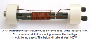 Baluns can be wound on a ferrite core using insulated wire, which can be held in place with cable ties. Laquered copper wire can also be used, but this is more difficult to apply since it is less flexible. When winding laquered copper wire onto a ferrite rod, be careful not to apply too much force in shaping the wire, because ferrite rods are a brittle ceramic and break easily!
(Updated 1 Jan. 2011) The balun's properties at various frequencies (i.e. its usable bandwidth) are determined by two factors: the inductance of the windings, and the capacitance between the windings. The latter can be especially detrimental at the higher frequencies. The capacitance can be reduced by increasing the spacing between the windings. Some experimentation with varying numbers of windings at different spacings may be necessary to find the optimum configuration in a particular situation.
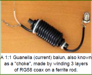 Often a "choke" to suppress coaxial shield currents (i.e. a 1:1 Guanella balun) is made by winding the coaxial cable into 10 or 12 loops, either at the antenna or at the foot of the tower. Generally this is not very effective. On low frequencies the impedance of the coil (which is essentially wound on an air core with very low permeability) is insufficient. On higher frequencies the capacitance between the windings (made worse by the fact that both ends of the coil are usually close together) becomes a problem.
A better 1:1 Guanella (a.k.a. choke) balun can be made by winding an odd number of layers of coax onto a ferrite rod. The ferrite's permeability is much higher than that of air, which improves its performance on the higher bands. The opposite ends of the coil are on opposite ends of the rod, which reduces capacitance and improves performance on the higher bands. A balun with low capacitance, intended for use on the high bands (e.g. 10m and 6m) may be constructed from coax wound onto a toroid core as shown in the photo. Note the spacing and the direction of the windings. The size and permeability of the toroid (which determines when magnetic saturation will occur) and the breakdown voltage of the coax determine the maximum power level this balun can handle. When teflon-based coax and a large powdered iron core are used, baluns constructed in this manner can easily handle several kW. (Note: a balun faced with a serious impedance mismatch will saturate and overheat at lower power levels than one that "sees" the correct impedance at both sides!) (End of update.)
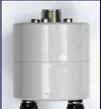
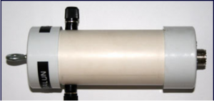
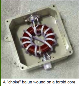 Baluns are generally easy to build. If they are intended for outdoor use, they need to be weatherproofed. A good way to do this is to use plastic drain pipe, which can be cheaply obtained from a local plumber, along with matching end caps. Baluns wound on ferrite rods can be housed in pieces of pipe with a length of 10-20cm (depending on the size of the rod) while toroids may be housed in short sections of pipe which essentially only serve to hold two end caps tightly together. A small amount of silicone sealant can provide further waterproofing. Use as little sealant as possible, so that you can remove the end caps later if repairs or changes should be necessary.
Baluns for indoor use can be housed in just about any enclosure that is on hand. Plastic is preferable, though. If metal housings are used, ensure that all wires and cores are kept well clear of any metal parts.
Winding diagrams
Below are the generic winding diagrams for typical balun types. The number of windings is intended as a starting point only. The ideal number depends on the desired frequencies and bandwidth, as well as on the core material used, i.e. the ferrite or powdered iron mix. The bandwidth can be changed by varying the spacing between the windings. Some experimentation may be necessary.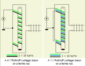
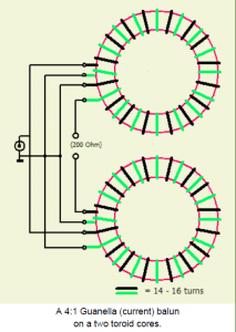
(This article was compiled over time from many different sources in literature and on the Internet. Special thanks to PAØFRI.)